Setting up a WiFi Bridge
In the following small documentation, we describe the simple setup of a stable point-to-point WiFi connection/bridge.
Setting up a point-to-point WiFi connection:
Traditionally, a point-to-point WiFi connection (also called a WiFi bridge) is used to connect two locations. This usually involves the use of directional antennas installed at the respective locations and aligned with each other. In special cases, sector or omnidirectional antennas can also be used.
Thanks to advancements in technology and industry developments, point-to-point connections can now be established over very long distances. Connections exceeding 30 km are achievable under optimal conditions.
Requirements for a stable point-to-point connection:
The key requirement for a truly stable WiFi bridge with high data throughput is a clear line of sight between the involved components. WiFi signals/radio waves are highly sensitive. Therefore, the components should always be installed outdoors and, depending on the specific needs and local conditions, at an appropriate height.
For short distances, say up to 250 m, it is less critical if a house wall obstructs the line of sight between the components. Our own tests have shown that even an entire roof structure may affect the signal but still allow for a stable connection.
However, entire buildings, concrete structures, or biomass such as trees or rocks will almost completely hinder the stable operation of the connection.
For longer distances (over 250 m), a clear line of sight is absolutely essential! Additionally, a clear Fresnel zone is also required. To keep it simple, we’ll skip detailed explanations here. In essence, you can assume that with an unobstructed line of sight, the Fresnel zone is also clear.
Which frequency band is best suited?
Which frequency band should be used for a point-to-point WiFi connection?
There are several frequency bands in Germany that can be used license-free. We will focus on the classic 2.4 GHz and 5 GHz frequency bands.
The 2.4 GHz band includes a total of 13 channels that can be used in Europe, but only three channels (1, 6, and 11) are truly non-overlapping and do not interfere with other channels. Furthermore, the 2.4 GHz WiFi frequency band is heavily utilized. Almost all private and public WiFi networks operate on this frequency band. In practical use, this can negatively impact a point-to-point WiFi connection in urban areas.
In contrast, in areas with few or no other WiFi networks, the use of the 2.4 GHz band is less problematic. The 2.4 GHz band, due to its longer wavelength compared to the 5 GHz band, is less susceptible to interference, and the components are generally more affordable.
The 5 GHz band, compared to the 2.4 GHz band, offers a total of 19 non-overlapping channels. The 5 GHz band is less commonly used in private and public WiFi networks due to its higher sensitivity to interference from factors like walls or ceilings. This makes 5 GHz components highly suitable for point-to-point connections in both urban areas and open spaces.
We generally recommend using 5 GHz components.
Which components/devices are best suited?
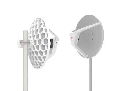
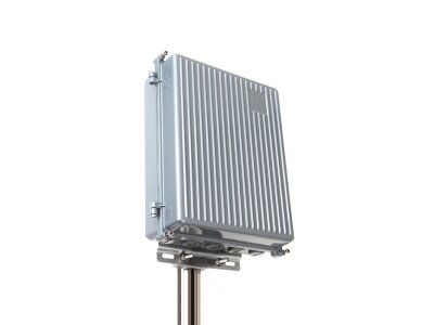
We typically recommend the use of so-called CPEs (Customer Premises Equipment)—active WiFi components that integrate the WiFi module and directional antenna. These components are usually housed in weatherproof enclosures and can operate in outdoor environments even under extreme temperature conditions. These WiFi components are connected to your local network via a standard Ethernet/network cable.
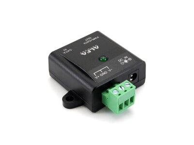
The power supply is provided using the PoE (Power over Ethernet) method. The components are powered via the same network cable that connects them to the network, eliminating the need for additional power cables and avoiding the use of separate antenna cables, which can cause signal losses. A PoE injector, typically included in the package, is used for this purpose.
We frequently use components from Ubiquiti Networks, as well as from LigoWave or MikroTik.
Ubiquiti components are more cost-effective. The devices are very user-friendly and operate stably even over longer distances. When the airMax AC protocol is enabled, actual data throughput of up to 450 Mbps can be achieved between two Ubiquiti components. For these cases, we recommend the NanoBeam 5AC-19, or for greater distances, the PowerBeam 5AC-500.
LigoWave components are slightly more expensive than Ubiquiti components. With the iPoll protocol enabled, data throughput of up to 500 Mbps can be achieved between two LigoWave components that comply with the AC standard. These devices are also very user-friendly and feature integrated triple lightning protection and dual firmware, ensuring reliability and durability. These components are especially well-suited for commercial applications. We recommend the LigoWave LigoDLB 5-20 AC for such scenarios.
Configuration:
Both components generally operate in bridge mode.
One of the two components involved in the point-to-point WiFi connection is set to access point mode. This is where you assign the SSID (the name of the WiFi network) and encryption settings. At this point, you should select WPA2 encryption.
The second component is set to station or client mode. Here, you simply select the WiFi network to connect to (choose the counterpart’s SSID from the previous step) and apply the same encryption settings.
Both components must be configured with appropriate IP addresses/subnet masks and, if necessary, gateway information, according to your network structure.
If you use the recommended Ubiquiti or LigoWave components, you can also enable the manufacturer-specific AirMax (Ubiquiti) or iPoll (LigoWave) protocol to maximize data throughput.
Both manufacturers offer additional configuration options, but these can generally remain at their default settings.
We are, of course, delighted if you purchase the recommended components from our online shop and hope this brief documentation has provided you with a straightforward and compact guide to assist with your purchase decision.

